gle/CDPU
Cockpit Display & Processing Unit
Main Features • High resolution 6.5” color LCD display*. • MS Windows-based software for easy system set-up and display control. |
Overview
gle/CDPU allows real time visualization of a selected subset of physical parameters directly acquired on the aircraft by the Flight Testing PCM data acquisition system or derived from calculations.
The visualization section and the data processing hardware have been kept separated in order to reduce the thickness of the display unit and to enable easier installation.
The CDPU comprises an high-resolution LCD display with a wide viewing angle and high luminance.
The user can easily recall on the screen one of the pre-defined page using the functional buttons of an external keypad.
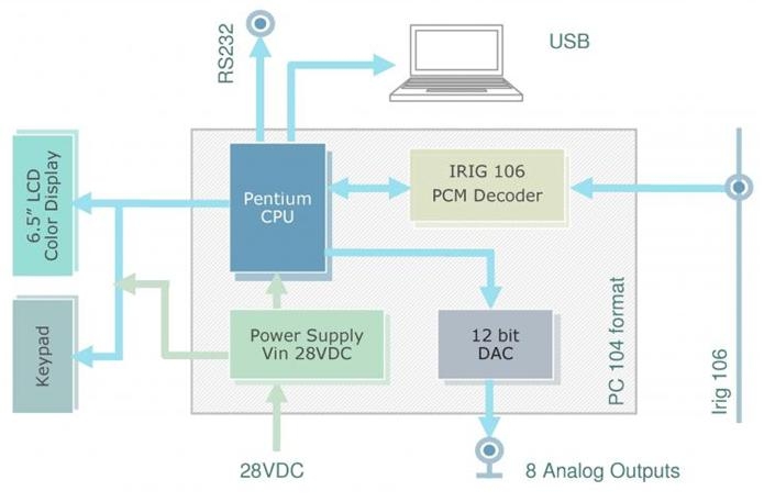
The CDPU features a PCM (IRIG 106 Ch. 4) decoder for NRZ-L + clock input format.
This is a programmable decommutator for PCM streams with data rate up to 5 Mbps.
A PC-104 processor board communicates with the decoder unit through ISA bus, converts input data in engineering units, executes the user-defined calculations starting from the input channels and drives the display section.
The unit can be provided with 8 analog outputs with 12 bits resolution.
The control and processing hardware (including the power supply) is enclosed in a compact, ruggedized aluminum box.
All the calculation and visualization options can be set via software by means of a proprietary software tool enabling user friendly operation in standard Windows environment.
Block Diagram
Technical Specifications
IRIG 106 PCM Decom
|
Input signal type |
NRZ-L+ clock |
|
Bit Rate |
Up to 5 Mbps |
|
Input levels |
Single-ended TTL and RS-422 |
|
Word length, bit order and parity |
Programmable |
|
Subframe sync |
SFID |
Control Unit
|
Industrial format |
PC 104 |
|
CPU |
Pentium Low Power (700MHz) |
|
Output Communication Ports |
RS232 and Ethernet 10/100 BaseT |
|
Operating system |
MS Windows XP Embedded |
|
Analog outputs |
8 channels;12bits resolutions |
|
Operating Temperature |
0° C ¸ 50° C |
|
Housing |
Ruggedized aluminum enclosure |
|
External dimension |
121 x 134 x 141 mm |
Display
|
Size |
6.5” (diagonal) |
|
Technology |
TFT active matrix color liquid crystal display (AMLCD) |
|
Display area |
139(H) x 103(V) mm |
|
Luminance |
300 cd/m2, typ |
|
Display colors |
262144 |
|
Contrast ratio |
250:1 typ |
|
Viewing angle |
H 50°(typ. Left and right side); V 35°(up side), 45°(down side) |
|
Operating Temperature |
0° C ¸ 60° C |
|
Maximum cable length |
10 meters |
|
External dimension |
196.6 x 142.8 x 40 mm |
Configuration Software
|
User friendly MS Windows GUI based software composed by 6 major sections which easily drive the user in defining the full parameters selection setup and all the visualization options. |
|
|
Frame Setup |
In this section the main characteristics of the Irig 106 stream can be defined like the format frame, the word length, the sync words and SFID properties. |
|
Parameter Setup |
The word selection and the main characteristics of the physical parameters to be extracted from the map can be set in this worksheet in a very user friendly environment. It is mainly formed by a spreadsheet where each row corresponds to a selected channel with all the related properties describing its position inside the map. The addition of channels which differ only for start word in the minor frame can be quickly done through the “Add Copies” button. Moreover it is possible to define on one-channel-basis the raw data linear conversion in engineering unit. |
|
Map Viewer |
This is a very useful tool that summarize the entire map structure and the inner parameters’ position as defined in the previous sections. It looks like a common worksheet where the selected channels have different colors and they can easily be identified through the zoom buttons. |
|
Virtual Channels Setup |
Besides physical channels, virtual channels obtained through calculations, can be added here to the list of the parameters to be displayed. The equation editor allows to create a formula just clicking on the needed physical channels from the list and selecting the desired operators. Nested formulas including both physical and virtual channels are also permitted. The available operations include algebraic, exp & log, trigonometric, statistical, bit handling and logic (L&R Shift, And..), format conversion (i.e. IntToFloat) built-in functions. Each parameter ‘s properties may be complete specifying the corresponding label and units. |
|
Visualization Setup |
Up to 12 different panels (parameters in alphanumeric format) can be defined choosing among 4 different display formats (i.e. 5x3, 3x3, 2x2. meshed 3x3+2x2). Page selection and scrolling is possible through the external keypad. The user can associate to each cell one parameter (physical or virtual) with a 6 digits visualization (sign + numbers), e.u. and label. On single channel basis the number of decimal places (0, 1 or 2), the eventual average of the last N samples and upper and lower thresholds (to change the cell color background in alarm mode) can be set in this section. Upon the displayed page type the font size is automatically scaled, while the refresh rate can be choose by the user (>=0.2 sec). |
|
DAC Setup |
This section enables users to set up to 8 different analog output channels which can be associate to any of physical or virtual channels defined in the other sections. Output levels are in the ±5V range and it is possible to scale them to desired values in engineering units on a single-channel basis. |
Options
|
gle/CDPU can be optionally equipped with different or auxiliary digital I/O interfaces. Inputs: RS 232/422, ARINC 573/717, ARINC 429, Mil-Bus1553 / Outputs: RS232/422. *Display Size: different size are available on request. |
Due to continuous developments, specifications are subject to change without prior notice. This product is not intended for applications whose its failure to perform can be expected to cause damages to properties and/or persons and/or injury to human life.